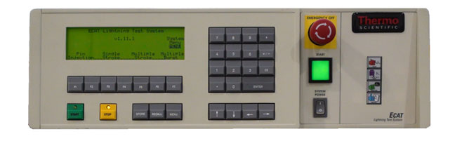
The M Precision Labs ECAT Lightning Test System (LTS) is a modular test platform which tests to the lightning simulator requirements of RTCADO-160, Section 22 and Section 17. The system is expandable to meet Boeing, Airbus, EUROCAE and other avionic standards.
- Safe
- Quick test set-up
- Simple user interface
- Waveforms: 1, 2, 3, 4, 5A, 5B and 6
- Levels 1, 2, 3, 4 and 5+
- Single Stroke, Multiple Stroke, Multiple Burst and Pin Injection from the same front panel
- Modular architecture
- Voltage spikes
When failure is not an option
With its fully-automated test operation, the M Precision Labs ECAT Lightning Test System (LTS) yields reliable, repeatable and accurate test results to avionics lightning simulation requirements of RTCA DO 160 Section 22 and 17. It is easily expandable to meet most Boeing, Airbus, EUROCAE and other requirements.
Building on the legacy of the proven ECAT platform, it provides field-upgradeable modular technology featuring fast test set- up, intuitive programming, and front panel control. On-site calibration and field service is available worldwide.
System description
The ECAT LTS is configured as a basic test system available as a Level 3, Level 4, or Level 5 tester. All test systems feature Single stroke, Multiple Stroke, Pin Injection and Multiple Burst test capability integral to the system controls without any external connections.
The system is composed of a frame that houses power and control functions for the system. Waveforms are produced from the modules inserted into the frame. Both the frame and modules can be purchased separately. Owning multiple frames allows increased capability by “swapping” modules between frames, and testing with each frame simultaneously.
The Total System
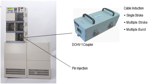
The ECAT LTS provides a modular test platform based on the requirements of RTCA DO-160G Section 17 (Voltage Spikes) and Section 22 (Lightning Induced Transient Susceptibility), EUROCAE, Boeing, Airbus and others. The LTS can perform Pin Injection, Cable Bundle and Ground Injection testing with Single Stroke, Multiple Stroke and Multiple Burst modes from the same module. The system can be expanded as test requirements evolve or to allow the operator to double his capacity using existing modules without purchasing another system.
Turn-key Testing
With the advent of the ECAT LTS, lightning testing of avionics comes of age with an easy to use, turn-key solution for test engineers and technicians. Until recently, the availability of commercial equipment for testing to lightning standards for avionics, such as RTCA DO-160G, has been limited. Most test equipment used in the industry was home-made: difficult and time consuming to set-up and awkward to use, often unsafe and requiring skilled engineers for their operation and maintenance.
Testing with the ECAT LTS insures repeatable, reproducible test results while virtually eliminating tester set-up time. Waveforms and functions are selected with the push of a button rather than by reconfiguring test equipment and moving around bulky generator boxes and wiring. The ECAT LTS can significantly reduce total test time resulting in significant cost savings.
Versatile, Modular Architecture
ECAT LTS modular systems are totally open-ended to protect you as industry standards evolve. Built upon the proven modular construction of the M Precision Labs ECAT System, ECAT LTS waveform simulators use plug-in modules that can be added or replaced by the operator at any time wi
Currently Available LTS Modules1:
| Waveform | Pin Injection | Single Stroke | Multiple Stroke | Multiple Burst | Description | Plug-in Module |
|---|---|---|---|---|---|---|
| WF1 | • | • | 6.4µs X 69µs Current Wave | D561, D566 | ||
| WF2 | • | • | • | ≤100ns x 6.4µs Voltage Wave | D562 | |
| WF3- 1 MHz | • | • | • | • | 1 MHz Oscillatory Voltage Wave | D563 |
| WF3- 10 MHz | • | • | • | 10 MHz Oscillatory Voltage Wave | D563 | |
| WF4 | • | • | • | 6.4µs X 69µs Voltage Wave | D561, D566 | |
| WF5A | • | • | • | 40µs X 120µs Current Wave | D561, D567 | |
| WF5A Airbus / Boeing | • | • | 40µs X 120µs Voltage & Current Wave | D568 | ||
| WF5B | • | • | • | 50µs X 500µs Current Impulse | D564 | |
| WF6 | • | 0.25µs X 4.0µs Current Impulse | D569 | |||
| Voltage Spikes | 2 | ≤2µs X ≥10µs, ≤2µs X ≥50µs, ≤2µs X ≥100µs, ≤2µs X ≥200µs, ≤2µs X ≥400µs |
D570 | |||
| 1 See specifications 2 Up to 50 pulses in 60 seconds | ||||||
One example of the multiple standards supported for WF3 Multiple Burst Test Mode:
| LTS Display | Standards Compliance | Min. Applic. Time | Max # Trans | Max # Bursts | Time Between Bursts | Time Between Transients |
|---|---|---|---|---|---|---|
| DO160 | DO160 Boeing D6-16050-5 Airbus ABD0100.1.2-F Airbus ABD0100.1.2-G |
3 sec | 20 | 3 | 30-300ms | 50-10,000µs |
| Airbus/E | Airbus ABD0100.1.2-E | 15 sec | 500 | 1 | ------------------ | 10-10,000µs |
| Boeing-4 | Boeing D6-16050-4 NH-90 | 3 sec | 20 | 24 | 10-200ms | 10-50µs |
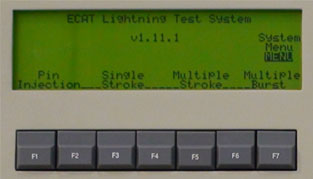
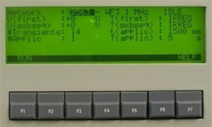
Example test setup for WF3 Single Stroke, Multiple Stroke, Multiple Burst and Pin Injection from the same module front panel
Controller front panel programming for above example
| 1. Select Test Type: Pin Injection, Single Stroke, Multiple Stroke or Multiple Burst | 2. Select waveform type, voltage levels and timing |
 |
 |
It doesn’t get any easier than this!
Model: F-LTS-X
| Model: F-LTS-X | (x indicates level 3, 4 or 5) |
|---|---|
| LTS Frame/Controller for the operation of individual modules | |
| System Voltage | 190-230 VAC, 50/60 Hz, 3Ø Wye, 30 Amax (Optional 190-230 VAC, 50/60 Hz, 1Ø 50 Amax) |
| Test Types | Single Stroke Multiple Stroke: 1-24 pulses; 10 – 200 ms fixed, random or irregular 1st pulse and subsequent pulse spacing Multiple Burst: 1-500 pulses; 50 – 1000 us fixed, random or irregular pulse spacing; 1-24 bursts; 30 – 300 ms fixed, random or irregular burst spacing Pin Injection Voltage Spikes |
| Number of Tests | 1 to 999 |
| Test Repetition Rate | 3 s to 255 s (at maximum level, min rep rate may be >3 s) |
| Control Interface | Display 8x40 character LCD; Remote USB, RS232, Fiber-optic (future feature) |
| Safety Features | Emergency off switch, external interlock for users (mats, Lexan barrier, etc); lockout/tag out capability |
| Module Bays | 3 full-width / 4 half-width plug-in module capability |
| Operating Temperature | +15°C to +35°C |
| Humidity | 10-75%, non-condensing |
| Physical Specifications | Height 160 cm (66.6 in); Width 107 cm (42 in); Depth 69 cm (27 in); Weight 360 kg (800 lb) fully configured |
| Options | LTS-1PHASE: Adds a power converter to accept 190-230 VAC, 50/60 Hz, 1Ø 50 Amax to power the LTS |
| CE Marking | Safety and EMC Directives |
Model: D561-Lx
| Model: D561-Lx | (x indicates level 3, 4 or 5) |
|---|---|
| LTS Module for WF1, WF4, WF5A, full-width ECAT plug-in module | |
| WF1 (CI1, GI) | Single Stroke, 6.4/69 µs, 50-3800 A, 2000 Voc Multiple Strokes, 6.4/69 µs, 25-1200 A |
| WF4 (GI) | Single Stroke, 6.4/69 µs, 25-2000V, 2100 Asc Multiple Strokes, 6.4/69 µs, 10-600 V |
| WF4 Pin Injection | 6.4/69 µs, 50-2000 Voc /10-400 Asc = 5 Ohm |
| WF5A (CI1, GI) | Single Stroke, 40/120 µs, 50-10000 A, 1300 Voc Multiple Strokes, 40/120 µs, 30-1500 A |
| WF5A Pin Injection | 40/120 µs, 50-1800 Voc /50-1800 Asc = 1 Ohm |
| Safety Features | Door interlocks, safety sockets, outputs only connected during transient, active module indicator LED, voltage present indicator LED |
| Operating Temperature | +15°C to +35°C |
| Humidity | 10-75%, non-condensing |
| CE Marking | Safety and EMC directives |
| 1(For Cable Induction use Model DCI-1 Cable Induction Coupler) | |
Model: D562-Lx
| Model: D562-Lx | (x indicates level 3, 4 or 5) |
|---|---|
| LTS Module for WF2, half-width ECAT plug-in module | |
| WF2 (CI1, GI)2/td> | Single Stroke, 0.1/6.4 µs, 25-1920 V, 1700 Asc Multiple Strokes, 0.1/6.4 µs, 25-1200 V |
| Safety Features | Door interlocks, safety sockets, outputs only connected during transient, active module indicator LED, voltage present indicator LED |
| Operating Temperature | +15°C to +35°C |
| Humidity | 10-75%, non-condensing |
| CE Marking | Safety and EMC directives |
| 1 (For Cable Induction use Model DCV-1 Cable Induction Coupler and use 2 for Level 5) | |
| 2 (Add wire to clamp between ground planes) | |
Model: D563-Lx
| Model: D563-Lx | (x indicates level 3, 4 or 5) |
|---|---|
| LTS Module for WF3, 1 MHz and 10 MHz, full-width ECAT plug-in module | |
| WF3 (CI1, GI) | Single Stroke, 1 MHz, 25-4000 V, 160 Asc Multiple Strokes, 1 MHz, 25-2400 V Multiple Burst, 1 MHz, 25-2300 V Single Stroke, 10 MHz, 25-4000V, 60 Asc Multiple Strokes, 10 MHz, 25-2400 V Multiple Burst, 10 MHz, 25-2300 V |
| WF3 Pin Injection | 1 MHz, 30-4000 Voc /1.2-160 Asc = 25 Ohm |
| Safety Features | Door interlocks, safety sockets, outputs only connected during transient, active module indicator LED, voltage present indicator LED |
| Operating temperature | +15°C to +35°C |
| Humidity | 10-75%, non-condensing |
| CE Marking | Safety and EMC directives |
| 1 (For Cable Induction use Model DCHV-1 Cable Induction Coupler) | |
Model: D564-Lx
| Model: D564-Lx | (x indicates level 3, 4 or 5) |
|---|---|
| LTS Module for WF5B, full-width ECAT plug-in module | |
| WF5B (CI1, GI2) | Single Stroke, 50/500 µs, 150-6000 A, 900 Voc Multiple Strokes, 50/500 µs, 30-1500 V |
| WF5B Pin Injection | 50/500 µs, 50-1800 Voc /50-1800 Asc = 1 Ohm |
| Safety Features | Door interlocks, safety sockets, outputs only connected during transient, active module indicator LED, voltage present indicator LED |
| Operating temperature | +15°C to +35°C |
| Humidity | 10-75%, non-condensing |
| CE Marking | Safety and EMC directives |
| 1 (For Cable Induction use Model DCI-1 Cable Induction Coupler) 2 (DCI-1 clamp cal loop) |
|
Model: D566-Lx
| Model: D566-Lx | (x indicates level 3, 4 or 5) |
|---|---|
| LTS Module for WF1, 4, full-width ECAT plug-in module | |
| WF1 (CI1, GI) | Single Stroke, 6.4/69 µs, 50-3800 A, 2000 Voc Multiple Strokes, 6.4/69 µs, 25-1200 A |
| WF4 (GI) | Single Stroke, 6.4/69 µs, 25-2000V, 2100 Asc Multiple Strokes, 6.4/69 µs, 10-600 V |
| WF4 Pin Injection | 6.4/69 µs, 50-2000 Voc /10-400 Asc = 5 Ohm |
| Safety Features | Door interlocks, safety sockets, outputs only connected during transient, active module indicator LED, voltage present indicator LED |
| Operating Temperature | +15®C to +35®C |
| Humidity | 10-75%, non-condensing |
| CE Marking | Safety and EMC directives |
| 1 (For Cable Induction use Model DCI-1 Cable Induction Coupler) | |
Model: D567-Lx
| Model: D567-Lx | (x indicates level 3, 4 or 5) |
|---|---|
| LTS Module for WF5A, full-width ECAT plug-in module | |
| WF5A (CI1, GI2) | Single Stroke, 40/120 µs, 50-10000 A, 1300 Voc; Multiple Strokes, 40/120 µs, 30-1500 A WF5A |
| Pin Injection | 40/120 µs, 50-1800 Voc /50-1800 Asc = 1 Ohm |
| Safety Features | Door interlocks, safety sockets, outputs only connected during transient, active module indicator LED, voltage present indicator LED |
| Operating Temperature | +15°C to +35°C |
| Humidity | 10-75%, non-condensing |
| CE Marking | Safety and EMC directives |
| 1 (For Cable Induction use Model DCI-1 Cable Induction Coupler) 2 (For Ground Injection take from cal loop on DCI-1) |
|
Model: D568-L5
| Model: D568-L5 | (x indicates level 3, 4 or 5) |
|---|---|
| LTS Module for WF5A for Airbus/Boeing specifications, full-width ECAT plug-in module | |
| WF5A (SS, MS) | 40/120 µs, 50-2000 voltage & current, output impedance =1 Ohm |
| Safety Features | Door interlocks, safety sockets, outputs only connected during transient, active module indicator LED, voltage present indicator LED |
| Operating Temperature | +15°C to +35°C |
| Humidity | 10-75%, non-condensing |
| CE Marking | Safety and EMC directives |
| 1 (For Cable Induction up to 1500V/1500A use Model DCVI-1 Cable Induction Coupler and use 2 for Level 5, use 3 for 2000V/2000A) | |
Model: D569-Lx
| Model: D569-Lx | (x indicates level 3, 4 or 5) LTS Module for WF6, full-width ECAT plug-in module |
|---|---|
| WF6 (CIA1, GI) | Multiple Burst, 0.25/4.0 µs, 5-160 A, 4500 Voc |
| Safety Features | Door interlocks, safety sockets, outputs only connected during transient, active module indicator LED, voltage present indicator LED |
| Operating Temperature | +15°C to +35°C |
| Humidity | 10-75%, non-condensing |
| CE Marking | Safety and EMC directives |
| 1 (For Cable Induction use Model DCHV-1 Cable Induction Coupler) | |
Model: D570
| Model: D570 | (x indicates level 3, 4 or 5) |
|---|---|
| LTS Module for RTCA DO-160G, Section 17, Voltage Spikes, full-width ECAT plug-in module | |
| ≤2µs X ≥10µs | 50Ω or 100Ω |
| ≤2µs X ≥50µs | 5Ω or 10Ω |
| ≤2µs X ≥100µs | 5Ω or 10Ω |
| ≤2µs X ≥200µs | 5Ω |
| ≤2µs X ≥400µs | 5Ω or 10Ω |
| Safety Features | Door interlocks, safety sockets, outputs only connected during transient, active module indicator LED, voltage present indicator LED |
| Operating Temperature | +15°C to +35°C |
| Humidity | 10-75%, non-condensing |
| CE Marking | Safety and EMC directives |
Accessories
Option: DCI-1
| Option: DCI-1 | |
|---|---|
| Cable Induction Coupler for WF1, 4, 5A, 5B | |
| WF1 | 6.4/69 µs, >2000 VLimit, >5000 A Test |
| WF4 | See Technical Note #201 |
| WF5A | 40/120 µs, >1200 VLimit, >10,000 A Test |
| WF5B | 50/500 µs, >900 VLimit, >6000 A Test |
| Safety Features | Double insulated, safety sockets |
| Dimensions | Height 21.6 cm (8.5 in); Width 28.3 cm (11.1 in); Depth 34.3 cm (13.5 in) |
| Aperture | 3.8 cm x 7.6 cm (1.5 in x 3 in) |
| Weight | 48 kg (106 lb) |
| CE Marking | Safety and EMC directives |
Option: DCV-1
| Option: DCV-1 | |
|---|---|
| Cable Induction Coupler for WF2 (use 2 for Level 5) | |
| WF2 | 0.1/6.4 µs, >2000 VTest, >1700 A Limit |
| Safety Features | Double insulated, safety sockets |
| Dimensions | Height 14.2 cm (5.6 in); Width 12.7 cm (5.0in); Depth 31.8 cm (12.5 in) |
| Aperture | 3.8 cm x 5.1 cm (1.5 in x 2 in) |
| Weight | 13 kg (29 lb) |
| CE Marking | Safety and EMC directives |
Option: DCHV-1
| Option: DCHV-1 | |
|---|---|
| Cable Induction Coupler for WF3, 6 | |
| WF3/1 MHz | 1 MHz, >4000 VTest, >300 A Limit |
| WF3/10 MHz | 10 MHz, >4000 VTest, >20 A Limit |
| WF6 | 0.2/4µs, >4000 VLimit, >160 A Test |
| Safety Features | Double insulated, safety sockets |
| Dimensions | Height 14.2 cm (5.6 in); Width 12.7 cm (5.0in); Depth 31.8 cm (12.5 in) |
| Aperture | 3.8 cm x 5.1 cm (1.5 in x 2 in) |
| Weight | 13 kg (29 lb) |
| CE Marking | Safety and EMC directives |
Model: D591
| Model: D591 | |
|---|---|
| Powered Pin Decoupler Module for Powered Pin Injection, half-width ECAT plug-in module | |
| Operating AC Voltage | 0-244 VAC, 20 A |
| Operating DC Voltage | 0-285DC, 10 A |
| Operating Frequency | 0-400 Hz |
| Safety Features | Safety sockets |
| CE Marking | Safety and EMC directives |
Option: DCVI-1
| Option: DCVI-1 | |
|---|---|
|
D568-L5 Cable Induction Coupler for Airbus/ Boeing WF5A specifications. Includes lift and ground plane. Top is removable to allow cable bundle insertion within the coupler. Top section weight is 180 lb. Ground Plane is 0.06 AL sheet, 1” perforated overhangs for attachment to adjacent ground planes if needed. Calibration loop contains 1 turn. 2 DCVI-1 clamps required for obtaining waveforms up to 1500V / 1500A 3 DCVI-1 clamps required for obtaining waveforms at 2000V / 2000A |
|
| WF5A (SS, MS) | 40/120 µs, 50-2000 voltage & current |
| Safety Features | Double insulated, safety sockets |
| Transformer | |
| Dimensions | Height 34.3 cm (13.5 in); Width 41.9 cm (16.5 in); Depth 45.7 cm (18 in) cable length |
| Aperture | 6.4 cm x 10.9 cm (2.5 in x 4.3 in) |
| Weight | 362 kg (800 lbs) |
| Cart | |
| Lowered Height | 29.8 cm (11.75 in) |
| Raised Height | 92.7 cm (36.5 in) |
| Length | 90.1 cm (35.5 in) |
| Width | 59.69 (23.5 in) |
| Lift Time | 25 strokes |
| Capacity | 498.9 kg (1100 lbs) |
| Weight | 130.2 kg (287 lb) |
| DCVI-1 total weight = 493kg 1087 lb) | |
| CE Marking | Safety and EMC directives |
Option: D111-1
| Option: D111-1 | |
|---|---|
| 5 KA Current Probe suitable for all waveforms except WF5B | |
| Sensitivity | 0.1 Volt/Ampere +1/-0% |
| Output Resistance | 50 Ohms |
| Scope Coupling | 1 MΩ DC/AC |
| Maximum Peak Current | 5,000 Amperes |
| Useable Rise Time | 25 nanoseconds |
| Low Frequency 3dB Point Cut-off | 5 Hz |
| High Frequency 3dB Point Cut-off | 15 MHz |
| Operating Temperature | 0°C to +65°C |
| Output Connector | BNC |
| Weight | 1.7 kg (3.7 lb) |
Option: D301X
| Option: D301X | ||
|---|---|---|
| 50KA Current Probe suitable for WF5A, 5B | ||
| Sensitivity | 0.01 Volt/Ampere +1/-0% | |
| Output Resistance | 50 Ohms Scope Coupling, 1 MΩ DC/AC | |
| Scope Coupling | 1 MΩ DC/AC | |
| Maximum Peak Current | 50,000 Amperes | |
| Useable Rise Time | 200 nanoseconds Low Frequency 3dB Cut-off | 5 Hz |
| High Frequency 3dB Cut-off | 2 MHz | |
| Operating Temperature | °°C to +65°C | |
| Output connector | UHF (SO-239) | |
| Weight | 7.9 kg (17.5 lb) | |
Option: D5KV
| Option: D5KV | |
|---|---|
| Voltage Probe suitable for all Waveforms to 5KV Max. | |
| Input Voltage | 5 kV |
| Scope Coupling | 1 MΩ DC/AC |
| System Attenuation | 100:1, +/-2% |
| System Input Resistance | 50 MΩ Input |
| Capacitance | < 6 pF |
| System BW (-3 dB) | 400 MHz |
| Operating Temperature | 0 °C to +50 °C |
| Output Connector | BNC |
Option: DPI-1
| Option: DPI-1 | |
|---|---|
| Probe accessory kit suitable for all Waveforms to 5KV | |
| Safety Socket Dolphin Clips | |
| Safety Socket Crocodile Clips | |
| Safety Socket Pointed Probes | |
| Safety Socket Grabber Probes | |
| Safety Socket Lug Terminals | |
| Safety Socket Clip-On | |
| Safety Socket Cables | |
| Safety Socket Leads | |
| Safety Socket Plugs | |
Option: E000
| Option: E000 | |
|---|---|
| ECAT Half-width module bay blank for unused module bay locations (required if no module is present in the bay). Cannot be used in lowest module bays. Half-width ECAT plug-in module. | |
| CE Marking | Safety and EMC directives |
Option: E002
| Option: E002 | |
|---|---|
| ECAT Full-width module bay blank for unused module bay locations (required if no module is present in the bay). Full-width ECAT plug-in module. | |
| CE Marking | Safety and EMC directives |
Option: LTS-1PHASE
| Option: LTS-1PHASE | |
|---|---|
| AC converter that allows LTS to operate from a single phase instead of a 3 phase AC source. | |
| Input | 1Ø 208VAC +/-10%, 50/60 Hz, 50 Amax |
| Output | 3Ø 208VAC +/-10% 50/60 Hz, 30 Amax |
| Dimensions | Height 50.8 cm (20 in); Width 38.1 cm (15 in); Depth 33 cm (13 in) |
| Weight | 34 kg (75 lb) |
| CE Marking | Safety, EMC Directives and UL listed |
Option: LTS-CASTERS
| Option: LTS-CASTERS | |
|---|---|
| Add-on base for LTS with larger 5” casters to facilitate high threshold and/or aggressive ramp installations. Increases LTS caster ground clearance from 1.5” to 5” | |
| Dimensions | Height 25 cm (9.8 in); Width 107 cm (42 in); Depth 69 cm (27 in) |
| Weight | 34 kg (75 lb) |
Option: LTS
| Option: LTS | |
|---|---|
| Kit of commonly used components for Section 22 setups | |
| Qty = 1 | 39000µF, 100V bypass capacitor for DC Supply up to 50V, i.a.w. Fig. 22-17 |
| Qty = 1 ea of the following block Varistors: | EPCOS B40K130 130VAC/170VDC1, 40kA2 EPCOS B40K150 150VAC/200VDC1, 40kA2 EPCOS B40K275 275VAC/350VDC 1, 40kA 2 EPCOS B40K550 550VAC/745VDC1, 40kA2 |
| Qty = 1 ea of following Bidirectional TVS diodes: | Littlefuse AK10-058C 64-70V3, 10kA2 Littlefuse AK10-076C 85-95V3, 10kA2 Littlefuse AK10-170C 180-220V 3, 10kA2 Littlefuse AK10-240C 2250-285V3, 10kA2 |
|
1 Operating voltage. See EPCOS datasheet for complete specs 2 Peak Pulse Current with 8.20µs impulse 3 Reverse Breakdown Voltage. See Littlefuse datasheet for complete specs |
|
Option: LTS-100 A-LISN
| Option: LTS-100 A-LISN | |
|---|---|
| Line Impedance Stabilization Network | |
| Frequency | 10kHz – 400MHz |
| Supply Lines | Single Conductor |
| Current Rating: | 100A |
| Max Voltage Rating: | DC – 1200V, 60Hz – 800V, 400Hz – 400V, 800Hz – 230V; Includes 10µF by-pass capacitor |
| Power Connector | Superior Con Socket |
| RF Output Connector | Type N |
| Chassis Size | 15” X 9” X 7” |
| Manufacturer | Fischer Custom Communications, Model: FCC-LISN-5-100-02-DO-160F |
Option: LTS-50 A-LISN
| Option: LTS-50 A-LISN | |
|---|---|
| Line Impedance Stabilization Network | |
| Frequency | 10kHz – 400MHz |
| Supply Lines | Single Conductor |
| Current Rating: | 50A |
| Max Voltage Rating: | DC – 1200V, 60Hz – 800V, 400Hz – 400V, 800Hz – 230V; Includes 10µF by-pass capacitor |
| Power Connector | Multi-Contact Safety Socket |
| RF Output Connector | Type N |
| Chassis Size | 9” X 6” X 5” |
| Manufacturer | Fischer Custom Communications, Model: FCC-LISN-5-50-1-01-DO-160F |
© 2012 - M Precision Laboratories Inc. All rights reserved. Results may vary under different operating conditions. Specifications, terms and pricing are subject to change. Not all products are available in all countries. Please consult your local sales representative for details.